| U.S. Patent: 10066445, September 4, 2018 |
| European Patent: EP 3 389 919 B1, October 13, 2021 |
| Description: A Flared and Thickened End assembly for tubular joints to improve | |
| the fatigue performance and increase the fatigue life of tubular connections subjected cyclic loading such as connections encountered in but not limited to offshore steel catenary risers (SCRs) and steel lazy wave risers (SLWRs) |
| |
APPLICATION
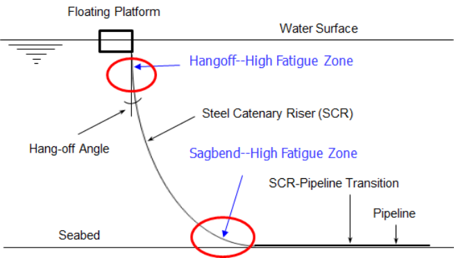
| One example is mitigating fatigue in SCRs and SLWRs |
BENEFITS
| Overcomes the limitation of traditional upset ends (which have the same ID as | |
| the pipe) imposed by the thickness that can be welded |
| Eliminates weld qualification of excessive wall thickness using traditional upset | |
| ends and associated risk, time, and cost |
| Reduces offshore welding time and cost |
| Provides an alternative to using costlier materials such as titanium |
| Provides an alternative to using non-established connections for steel catenay | |
| risers (SCRs) and steel lazy wave risers (SLWRs) |
| Renders simple SCRs with Flared and Thickened Ends a robust alternative to | |
| SLWRs |
BENEFITS OF SIMPLE SCRs WITH FLARED AND THICKENED
ENDS COMPARED TO SLWRs
| Significantly simpler to analyze and design (eliminate the effort and time | |
| required to establish the proper configuration of SLWRs and changes in configuration as a function of content variation and floater offsets) |
| Eliminate the high cost of buoyancy modules (several million US dollars) |
| Eliminate installation complexity, limitation on choice of installation methods and | |
| vessels, and associated high cost impact |
| No gaps in strakes which exist in the "hog bend" section of SLWRs (section with | |
| buoyancy modules) |
| Better short- and long-term integrity with no buoyancy modules to worry about | |
| especially for insulated risers and straked risers |
| Eliminate the environmental impact of buoyancy modules' raw materials, | |
| fabrication, shipping, and disposal |
FABRICATION
| Can be fabricated either as a separate forging or integral with the pipe |
| Fabrication as separate forgings requires WPQ, fatigue testing, and AUT | |
| qualification/validation of the |
| Pipe-to-forging welds | |
| Forging-to-forging welds |
| Fabrication integral with the pipe requires WPQ, fatigue testing, and AUT | |
| qualification/validation of the |
| Flared and Thickened End-to-Flared and Thickened End welds | |
| This would likely eliminate the WPQ, fatigue testing, and AUT | |
| qualification/validation of the SCR pipe welds--would definitely eliminate it for thickness of the integral Flared and Thickened Ends within certain code limits of the SCR pipe thickness |
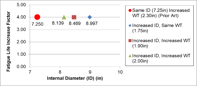
EXAMPLE
In this example, the SCR pipe is 7.25in ID X 1.75in WT. The fatigue life is low and
Flared and Thickened Ends are needed to provide a factor of 4 in order to meet the
design life.
| Keeping the same pipe ID (traditional upset ends) requires a 7.25in ID X 2.3in | |
| WT upset ends--this thickness is excessive for fatigue quality welding especially offshore |
| Keeping the same pipe wall thickness requires 8.997in ID X 1.75in WT flared | |
| ends--this increase in ID is probably excessive |
| Alternative Flared and Thickened Ends are |
| 8.469in ID X 1.90in WT--this increase in ID is more reasonable | |
| 8.139in ID X 2.00in WT--this increase in ID is yet more reasonable and the | |
| increase in WT is also reasonable for welding |
| Other Flared and Thickened End configurations are possible as desired |
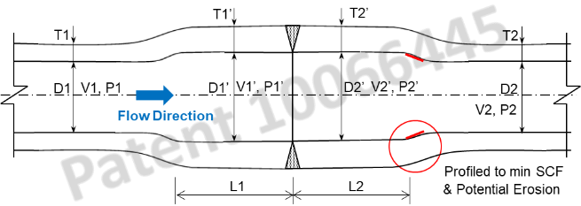
FLOW VELOCITY
| Q = V1 * A1 = V1’ * A1’ => |
- V1’ = V1 * (A1/A1’) = V1 * (D1/D1’)^2
| Thus, as the diameter increases, the velocity decreases |
| Example |
| SCR pipe: 7.25in ID X 1.75in WT | |
| Flared & Thickened Ends: 8.139in ID X 2.00in WT | |
| V1’ = 0.79 V1 |
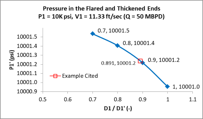
FLOW PRESSURE
| From Bernoulli’s Equation |
- P1 + ρ g h1 + ½ ρ V1^2 = P1’ + ρ g h1’ + ½ ρ V1’^2 =>
| P1’ = P1 + ρ g (h1 – h1’) + ½ ρ (V1^2 - V1’^2) |
| Thus, as the diameter increases, the pressure increases |
| Example |
| SCR pipe: 7.25in ID X 1.75in WT | |
| Flared & Thickened Ends: 8.139in ID X 2.00in WT | |
| ρ = 1.71 lb.sec^2/ft^4 (55 pcf oil) | |
| P1 = 10 ksi | |
| h1 – h1’ = ~ 2.5ft Length of Flared & Thickened Ends | |
| V1 = 11.33 ft/sec (corresponds to production of 50 Mbpd) | |
| V1’ = 8.95 ft/sec | |
| P1’ = 10.0012ksi |
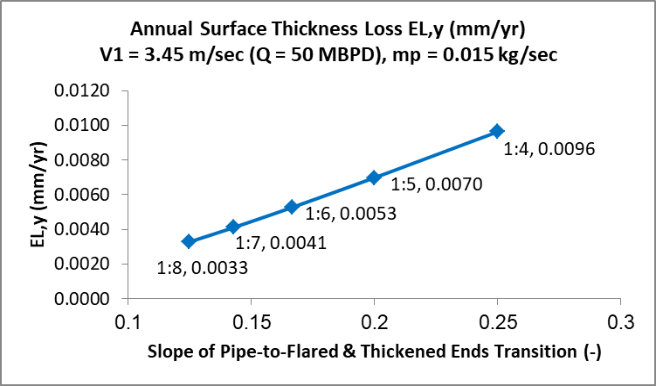
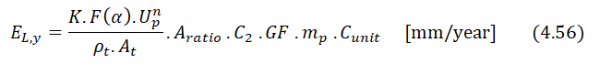
POTENTIAL EROSION
| Potential Erosion on Transition from Flared & Thickened Ends-to-Pipe |
| From DNVGL-RP-O501, annual surface thickness loss |
| Example |
| SCR pipe: 7.25in ID X 1.75in WT | |
| Flared & Thickened Ends: 8.139in ID X 2.00in WT | |
| ρm = 881 kg/m^3 (55 pcf Oil) | |
| ρt = 7800 kg/m^3 (487 pcf , steel pipe) | |
| P1 = 10 ksi | |
| V1 = 11.33 ft/sec (3.45 m/sec, corresponds to production of 50 Mbpd) | |
| V1’ = 8.95 ft/sec (2.73 m/sec), V1 is used conservatively | |
| mp = 0.015 kg/sec (0.033 lb/sec, mass rate of sand) | |
| dp = 0.0005 m (0.5mm, ~20 mils, sand particle diameter) | |
| As Velocity increases, measures to control mass rate of sand increase | |
| The transition thickness can be increased to accommodate potential erosion, e. | |
| g., 0.29mm for 30-yr riser life and 1:4 transition slope | ||
| Erosion is not an issue for export SCRs | |
| CFD analysis can be performed for better prediction of potential erosion |
IMPACT ON FLOW
The impact of the Flared and Thickened Ends on the flow is negligible (if any) for
| The Flared and Thickened Ends will be placed in the high fatigue zones such as | |
| the sagbend and hangoff, i.e. their number will be small (e.g. ~13 for a 500ft long high fatigue zone in the sagbend--not considering multi jointing) |
| The Flared and Thickened Ends will be in the "vertical" section of the SCR |
| The "smooth" transition from pipe to Flared and Thickened Ends | |

| PATENTS |
| TUBULAR CONNECTION ASSEMBLY FOR IMPROVED FATIGUE PERFORMANCE OF METALLIC RISERS |
| | | | | | | |
| ARTIFEX ENGINEERING INC. |
| ARTIFEX ENGINEERING INC |